


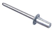
Closed End Blind Rivets

Closed-End Blind Rivets: Dome Head and Countersunk Head Styles
Jay-Cee Sales and Rivet Inc. offers a large selection of closed end blind rivets, including dome head and countersunk styles. For more information or to place your order call us today.
Closed-End Blind Rivets Dome Head Specifications
Dimensions of Dome Head Style Break Mandrel Closed End Blind Rivets (Table 1)
| Rivet Series NO. | Nom Rivet Size | D | H | E | R | W | P | F | L | ||
|---|---|---|---|---|---|---|---|---|---|---|---|
| Body Dia | Style 1 Regular Head | Radius of Fillet | Mandrel Dia | Mandrel Protrusion | Blind Side Protrusion | Rivet Body Length | |||||
| Head Dia | Head Height | All Materials | |||||||||
| Max | Min | Max | Min | .Max | Max | Min | Max | Max | |||
| 4 | 1/8 (.125) | 0.128 | 0.122 | 0.252 | 0.224 | 0.050 | 0.025 | 0.074 | 1.00 |
Equal to "L" Rivet Body Length |
See Table 2 |
| 5 | 5/32 (.156) | 0.159 | 0.153 | 0.328 | 0.296 | 0.065 | 0.025 | 0.092 | 1.06 | ||
| 6 | 3/16 (.187) | 0.191 | 0.183 | 0.394 | 0.356 | 0.080 | 0.025 | 0.110 | 1.06 | ||
| 8 | 1/4 (.250) | 0.255 | 0.246 | 0.525 | 0.475 | 0.100 | 0.025 | 0.146 | 1.06 | ||
| See Notes | 3 | 4 | |||||||||
Notes:
- All Dimensions are in inches.
- For application data, see table 2
- The Junction of head shank shall have a fillet with a max radius as shown.
- The blind side protrusion (F) equals the max length of rivet body (L) as given in Table 2 for the applicable grip. Minimum blind side clearance may be calculated by subtracting the actual grip (G) (i.e. the total thickness of material to be joined) from the blind side protrusion (F). (Example: To join two plates each .100 in. thick with a 5/32 in. rivet, a No. 54 rivet would be used. Minimum blind side clearance necessary to permit proper rivet setting would be L-G, which is .500 - .200 and equals .300 in.)
Application Data for Dome Head Style Break Mandrel (Table 2)
| Rivet Series NO. | Nom Rivet Size | Recommended Drill Size | Recommended Hole Size | Rivet No. | Grip Range |
Rivet Body Length | |
|---|---|---|---|---|---|---|---|
| Max | |||||||
| Max | Min | ||||||
| 4 | 1/8 (.125) | #30 | 0.133 | 0.129 |
41 42 43 |
.020-.062 .063-.125 .126-.187 |
0.297 0.360 0.422 |
|
44 45 46 48 |
.188-.250 .251-.312 .313-.375 .376-.500 |
0.485 0.547 0.610 0.735 |
|||||
| 5 | 5/32 (.156) | #20 | 0.164 | 0.160 |
52 53 54 |
.020-.125 .126-.187 .188-.250 |
0.375 0.437 0.500 |
|
55 56 58 |
.251-.312 .313-.375 .376-.500 |
0.562 0.625 0.750 |
|||||
| 6 | 3/16 (.187) | #11 | 0.196 | 0.192 |
62 64 |
.020-.125 .126-.250 |
0.406 0.531 |
|
66 68 610 612 |
.251-.375 .376-.500 .501-.625 .626-.750 |
0.656 0.781 0.906 1.026 |
|||||
| 8 | 1/4 (.250) | F | 0.261 | 0.257 |
82 84 86 |
.020-.125 .126-.250 .251-.375 |
0.445 0.570 0.695 |
|
88 810 |
.376-.500 .501-.625 |
0.820 0.945 |
|||||
| See Notes | 2 | ||||||
Notes:
- All Dimensions are in inches.
- Recommended drill sizes are those which normally produce holes within the specified hole size limits.
Dome Head Closed-End Blind Rivets
PR--AAPH (Aluminum Rivet / Aluminum Mandrel)
PR--ASPH (Aluminum Rivet / Steel Mandrel)
PR--FFPH (Stainless Steel Rivet / Stainless Steel Mandrel)
Example: PR64FFPH
Closed-End Blind Rivets Countersunk Head Specifications
Dimensions of 120 Deg. Countersunk Head Style Break Mandrel Closed End Blind Rivets (Table 1)
| Rivet Series NO. | Nom Rivet Size | D | H | E | R | W | P | F | L | ||
|---|---|---|---|---|---|---|---|---|---|---|---|
| Body Dia | Style 1 Regular Head |
Radius of Fillet | Mandrel Dia | Mandrel Protrusion | Blind Side Protrusion | Rivet Body Length | |||||
| Head Dia | Head Height | All Materials | |||||||||
| Max | Min | Max | Min | .Max | Max | Min | Max | Max | |||
| 4 | 1/8 (.125) | 0.128 | 0.122 | 0.252 | 0.221 | 0.0420 | 0.025 | 0.074 | 1.00 | Equal to "L" Rivet Body Length | See Table 2 |
| 5 | 5/32 (.156) | 0.159 | 0.153 | 0.328 | 0.296 | 0.051 | 0.025 | 0.092 | 1.06 | ||
| 6 | 3/16 (.187) | 0.191 | 0.183 | 0.394 | 0.356 | 0.060 | 0.025 | 0.110 | 1.06 | ||
| 8 | 1/4 (.250) | 0.255 | 0.246 | 0.525 | 0.475 | 0.080 | 0.025 | 0.146 | 1.06 | ||
| See Notes | 3 | 4 | 5 | ||||||||
Notes:
- All Dimensions are in inches.
- For application data, see table 2
- Maximum head diameter is called on nominal rivet diameter and nominal head angle extended to sharp corner. Minimum head diameter is absolute
- Head Height is given for reference purposes only. Variations in this dimension are controlled by the diameters (H) and (D) and the included angle of the head.
- The blind side protrusion (F) equals the max length of rivet body (L) as given in Table 2 for the applicable grip. Minimum blind side clearance may be calculated by subtracting the actual grip (G) (i.e. the total thickness of material to be joined) from the blind side protrusion (F). (Example: To join two plates each .100 in. thick with a 5/32 in. rivet, a No. 54 rivet would be used. Minimum blind side clearance necessary to permit proper rivet setting would be L-G, which is .550 - .200 and equals .350 in.)
Application Data for Countersunk Head Style Break Mandrel (Table 2)
| Rivet Series NO. | Nom Rivet Size | Recommended Drill Size | Recommended Hole Size | Rivet No. | Grip Range |
Rivet Body Length | |
|---|---|---|---|---|---|---|---|
| Max | |||||||
| Max | Min | ||||||
| 4 | 1/8 (.125) | #30 | 0.133 | 0.129 |
41 42 43 |
.031-.062 .063-.125 .126-.187 |
0.332 0.395 0.457 |
|
44 45 46 48 |
.188-.250 .251-.312 .313-.375 .376-.500 |
0.520 0.582 0.645 0.770 |
|||||
| 5 | 5/32 (.156) | #20 | 0.164 | 0.160 |
52 53 54 |
.063-.125 .126-.187 .188-.250 |
0.425 0.487 0.550 |
|
55 56 58 |
.251-.312 .313-.375 .376-.500 |
0.612 0.675 0.800 |
|||||
| 6 | 3/16 (.187) | #11 | 0.196 | 0.192 |
62 64 |
.063-.125 .126-.250 |
0.471 0.601 |
|
66 68 610 612 |
.251-.375 .376-.500 .501-.625 .626-.750 |
0.736 0.851 1.026 1.101 |
|||||
| 8 | 1/4 (.250) | F | 0.261 | 0.257 |
82 84 86 |
.020-.125 .126-.250 .251-.375 |
0.525 0.650 0.775 |
|
88 810 |
.376-.500 .501-.625 |
0.900 1.025 |
|||||
| See Notes | 2 | ||||||
Notes:
- All Dimensions are in inches.
- Recommended drill sizes are those which normally produce holes within the specified hole size limits.
Countersunk Head Closed-End Blind Rivets
PR--AACH (Aluminum Rivet / Aluminum Mandrel)
PR--ASCH (Aluminum Rivet / Steel Mandrel)
PR--FFCH (Stainless Steel Rivet / Stainless Steel Mandrel)
Example: PR64FFCH